What is Arc Flash Analysis?
An arc flash analysis is essentially a risk assessment of a particular environment within a workplace that determines what arc flash hazards are present. Employers are required to conduct these assessments in order to ensure that their workers understand the risks posed to them and how best to protect against them.
The central question that an arc flash analysis seeks to answer is, how big would the bang be in the event of an electrical explosion? By knowing this, companies can adequately protect their employees against the arc flash risks that are present in their work environment by issuing them with the correct personal protective equipment (PPE).
An Arc Flash analysis identifies areas of low risk, as well as those at high risk of an arc flash incident. This allows employers to tailor their arc flash protection strategy accordingly. An analysis also assess the potential severity of injury at a given distance and locates the protection boundary at which there is a severe danger of second degree burns occurring.
There are many facets to a successful arc flash analysis and generally, they are adapted to fit the specific industry and requirements of a company. They can include arc flash calculations, comprehensive site surveys and fault level studies.

Who can perform an Arc Flash Analysis?
An arc flash analysis should only be performed by experienced and qualified electrical engineers familiar with power quality, short circuit studies, NFPA 70E, and IEEE 1584.
The person performing the analysis can be an in-house electrical engineer, from an external electrical engineering firm, or ideally, from a specialist arc flash analysis company.
In order to properly identify and calculate Arc Flash Incident Energy certain steps need to be done. Here are some key reference points:
- IEEE 1584 - IEEE Guide for Performing Arc-Flash Hazard Calculations
- 1 IEEE Guide for the Specification of Scope and Deliverable Requirements for an Arc-Flash Hazard Calculation Study in Accordance with IEEE Std 1584™
- Practical experience
What is the Arc Flash Analysis Process?

We can bring recommended steps into analysis and calculations. Recommended steps will allow you to identify Arc Flash Incident Energy, Arc Flash Boundary and will provide recommendations for improvements. While IEEE1584 and IEEE1584.1 already provides useful guides, I adjusted it a bit more based on my experience to show how to go through Arc Flash Analysis in the most useful and practical way.
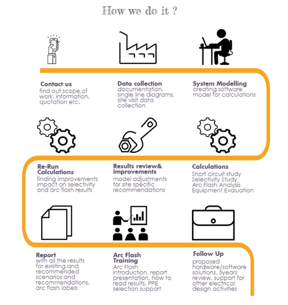
How to Perform an Arc Flash Analysis in 16 Steps
The first 8 steps are minimum to identify existing Arc Flash Incident Energy in our electrical system. It is acceptable but there is a better way, at MR Power Tech their aim is to identify and improve situations at customer installation thus it is good practice to include further steps. This means to adjust model a bit more to allow for best solutions and cover topic from A to Z.
Here is an overview of all steps:
Step 1. Scope of Study
Which part of the installation? What is the goal? Improvements approach
Step 2. Data Collection
Collect data by visiting the site, gathering documentation and creating operation scenarios
Step 3. System Modelling
- 3a. Determine enclosure type, dimensions and typical gap
- 3b. Determine electrode configuration
- 3c. Determine working distance
- 3d. Model protective device characteristics
Step 4. Perform Short Circuit Current Analysis
IEC 60909, ANSI, IEC 61660 (DC) etc.
Step 5. Perform Selectivity Analysis
Existing situation identification, creating a reference base for recommendations and comments
Step 6. Equipment Withstand Rating Evaluation
Verify if the Switchgears, Breakers, Fuses are within calculated short circuit currents
Step 7. Perform Arc Flash Analysis
Existing situation results and comments for improvements in line with the scope of work acc. IEEE-1584-2018 (Germany - DGUV Information 203-077)
Step 8. Review Results
Verification of all identifies issues related to system protection, selectivity, withstand rating and Arc Flash Hazard
Step 9. Perform Selectivity Analysis
Recommendation for improvements of protective device settings, suggestions for hardware and software modernizations or exchange.
Step 10. Perform Arc Flash Analysis
Recommendations related to selectivity analysis, possible improvements by using available techniques in line with the scope of work
Step 11. Final Report
Create a Final Report which Includes all results, comments, assumptions and recommendations
Step 12. Arc Flash Training
On-site training at the customer's location to identify needs for knowledge and discussion about safety. Learn more about arc flash training here.
Step 13. Equipment Labelling
Installing labels on the equipment during the site visit or allow the customer to do it. Learn more about arc flash labelling here.
Step 14. Arc and FR PPE Selection
Source solutions with Arc Flash and Flame Resistant PPE Provider ensuring the clothing meets the project requirements. See our Collection of Arc Flash and FR Clothing here.
Step 15. Recommendations, Follow up and Actions
All activities related should provide recommendations, supporting electrical engineering design activities based on the model
Step 16. Review every 5 years or every major change
Maintaining and keeping the model up to date. Ensuring all the latest standards are up to date after any modifications or changes.
What is Scope of Work for an Arc Flash Analysis?
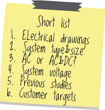
In the initial phase before Arc Flash Analysis it is important to identify scope of work. Below I highlighted few most common things that will have the biggest impact:
- Customer specific targets (system retrofit, specific safety issues, modernization etc)
- Which part of installation? (complete system or part only)
- System voltage LV, MV or HV
- AC only or AC&DC
- Type of Facility (test lab, marine, data centre, industrial etc)
- Type of DC installation (BESS, UPS, UPSaaR, DRUPS, DC motors, DC generators etc)
- Operation scenarios, possible system configurations
- Related customers procedures (EHS, arc flash corporate rules)
- Any other relevant information’s
Where to find the information?

Our next step is to have a kick-off discussion between Power System Engineer and a customer. This is so far the easiest way to explain important details and identify scope of work for Arc Flash Analysis. To assess scope of work we need information which can be found in:
- Documentation (previous studies, load schedules, instructions)
- Single Line Diagrams with MV and LV network data
- Any excel load lists, motors lists
- EHS instructions or procedures
- Site specific requirements and documents
What are limitations for Arc Flash Analysis?
It is very good if installation falls into IEEE 1584 Model Range, which is:
- 208 V to 600 V: 500 A to 106 000 A (AC)
- 601 V to 15 000 V: 200 A to 65 000 A (AC)
Above 15kV we will follow EPRI or ArcPro (OSHA 1910.269) based guidance up to 800kV system range however supply voltage above 15kV for industrial application happens only in specific situations. Practical rules for Arc Flash evaluation limits looking from protective device perspective is to start from (or stop at):
- LV circuit breaker ≥63A 3P (MCB, MCCB)
- LV fuse ≥ 100A
- LV Motors≥ 50HP (37kW)
- MV system up to 15kV (*>15kV EPRI/ArcPro OSHA 1910.269)
- DC systems up to 1000VDC
What to do when there is no documentation or it is very limited?
We have two options:
- Wait for documentation update (longest)
- Arrange site visit for system estimation (fastest)
System estimation visit goal is to do a fast review of installation and collect information’s about:
- Size of the electrical system
- Condition of the installation
- Type of the equipment
- Amount of the equipment
Lack of documentation is an obstacle but for experienced engineer after such visit it should be possible to provide reasonable estimation on cost and general follow up plan. Missing documentation is less comfortable situation for installation owner thus it is good to have flexible approach and provide support.
What is system mapping?
If no or little documentation exists it is necessary to made it. Since Arc Flash Analysis requires some specific data to be collected it is good idea to arrange data collection with system mapping. So what is system mapping? It is simply creating single line diagram of the system (MV to LV feeders). This process and can take days or weeks depending on system size. It has an important additional value as it can be combined with data collection for arc flash analysis. Thus it will save time and money providing valuable system overview and all details necessary for further analysis.

(Figure 1. Example of Single Line Diagram)
If you need support performing Arc Flash Analysis click here.
Prepared by Marcin Ruta Power System Engineer at MR Power Tech - marcinruta@mrpowertech.com - M: +31 616 243 335


